Laboratory Publications Department No. PTP-88
"This document contains information of a proprietary nature. ALL
INFORMATION CONTAINED HEREIN SHALL BE KEPT IN CONFIDENCE.
No information shall be divulged to persons other than IBM employees
authorized by the nature of their duties to receive such information,
or individuals or organizations who are authorized in writing by the Department
of Engineering or its appointee to. receive such information. "
Distributed to WHQ executives, managers of laboratories, assistant
managers of laboratories, and other engineering management personnel.
Further distribution must be cleared through these people.
June 20, 1956
PRESENTED AT THE SYRACUSE UNIVERSITY
JOINT ENGINEERING MEETING
June 17-22, 1956
International Business Machines Corporation
Endicott, New York
THE IBM WORLD WIDE ACCOUNTING MACHINE
(WWAM)
Contents
INTRODUCTION. . . . . . . . . . . . . . . . . . . . . . .

LOGIC CONSIDERATIONS OF THE WWAM . . . . . . . . . . . .

WWAM INPUT MECHANISM. . . . , . , . , . . , . , . . , . .

ARITHMETIC UNIT OPERATION AND STORAGE ADDRESSING  . . . .

THE PRINT EDIT FUNCTION. . . . . . . . . . . . . . . . .

SELECTOR OPERATION. . . . . . . . . . . . . . . . . . . .

THE WWAM SYSTEM. . . . . . . . . . . . . . . . . . . . .

CONCLUSIONS. . . . . . . . . . . . . . . . . . . . . . .
INTRODUCTION
The World Wide Accounting Machine (WWAM) was born mainly from the competition
the Bull Gamma is giving IBM in Europe. The Bull Gamma is a calculator
hooked normally to an accounting machine. IBM France has tried many different
approaches to meet this competition. The most important was the combination of an
expanded 604 to the double feed 441 Accounting Machine. This, however, did no
more than service a given number of installations. The basic problem still remained.
Then a year ago a selected group of men representing Engineering and Product
Planning from Poughkeepsie, Endicott, and San Jose went to Germany to find
the best way to develop an accounting machine capable of successfully solving this
competition problem and also give IBM a lead in the field which would last for some
years. After a few meetings, in which men from the German as well as from the
French organization were cooperating, it was decided that a transistorized serial
logic hooked up to a serial parallel printer provided the best approach. The transistorized
serial logic with core storage was chosen because a more classical
approach, an electromechanical parallel system, was not expandable and could
not provide enough compute capacity. The serial parallel printer chosen was the
stick printer because it has engraved printing, it is expandable, and is of lower
cost than other similar printers.
If to make a decision on the printer was an easy job, we cannot say the same
for pinpointing the specific type of serial logic which could best perform accounting
machine functions. Three different types of logic were considered at that time. In
Germany it was impossible to decide which was best suited for the job. A more
thorough investigation was required which took place in Poughkeepsie from September
to December, 1955. Two of the logics considered were of the fixed work length type
while the third was a variable word length approach.
LOGIC CONSIDERATIONS OF THE WWAM
Although it seemed that the competition was centered around fixed word length
versus variable word length, I would like to consider it another way. In the case of
the WWAM, the fixed word length logics represented the more or less classical
approach of making an accounting machine by hooking a printer to a computer. The
reasons for such an approach are quite obvious. A computer, if with enough capa-
city, is flexible enough to do any kind of computation and thus should be able to per-
form accounting jobs easily.
However, in the comparison below we can see that an accounting machine
handles jobs in a quite different manner from a calculator.
- 1-
| CALCULATOR
| ACCOUNTING MACHINE
|
| USUALLY DEALS WITH SINGLE INDEPENDENT CARDS
| USUALLY DEALS WITH GROUPS OF CARDS
|
| RESULTS ARE PUNCHED IN THE SAME CARDS
| PRINTED REPORTS ARE THE RESULTS
|
| CARDS ARE USUALLY OF A SINGLE FORMAT
| CARDS OF SEVERAL DESIGNS INVOLVED IN A SINGLE JOB
|
| PUNCHING REQUIRES ALMOST NO EDITING
| PRINTING IS ESSENTIALLY AN EDITING JOB
|
| COMPLICATED COMPUTATIONS
| SMALL AND SIMPLE COMPUTATIONS
( MOSTLY ACCUMULATION )
|
| -
| -
|
| BECAUSE Of THE ABOVE,
| BECAUSE OF THE ABOVE
|
| EDITING IS A MINOR FUNCTION
| EDITING IS THE MAJOR FUNCTION
|
From these considerations it thus looks that an accounting machine should
first be able to edit properly. The diagram that follows indicates the information
flow of an electromechanical accounting machine.
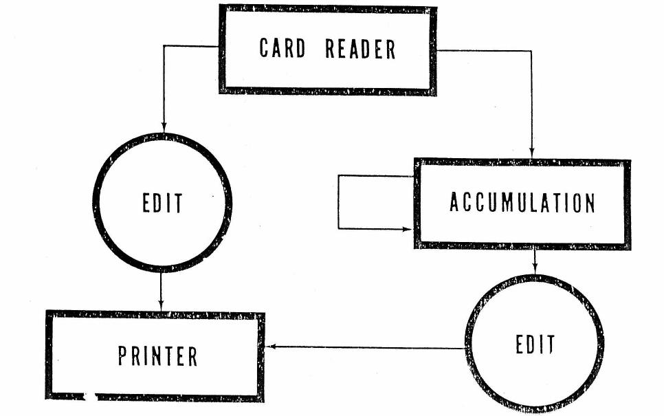 INFORMATION FLOW IN A SIMPLE ACCOUNTING MACHINE
In this machine, editing is performed by the positioning wiring in the control
panel. Editing is modified from line to line through the use of selectors. This
results in complex wiring in these control panels. When a printer is hooked up to
a calculator, the computing functions of the accounting machine are certainly improved
by going to serial programming. However, the editing function, which is
the most important function of the accounting machine, remains to be performed the
old way, as we can see in the following diagram.
- 1-
INFORMATION FLOW IN A SIMPLE ACCOUNTING MACHINE
In this machine, editing is performed by the positioning wiring in the control
panel. Editing is modified from line to line through the use of selectors. This
results in complex wiring in these control panels. When a printer is hooked up to
a calculator, the computing functions of the accounting machine are certainly improved
by going to serial programming. However, the editing function, which is
the most important function of the accounting machine, remains to be performed the
old way, as we can see in the following diagram.
- 1-
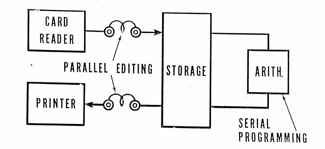
CALCULATOR WITH PRINTER OUTPUT
Since it is recognized that what makes a computer so easy to program is
precisely the serial type of programming, if the editing function of an accounting
machine could be performed in a serial fashion a real improvement would have
been obtained in the accounting machine field. We can see from the diagram
below that we tried to move the editing out of the input and output system and
bring it to a similar position as the arithmetic unit in order to have a serial editing.
The moment we do this, we suppress the control panel between the input-output and
the storage.
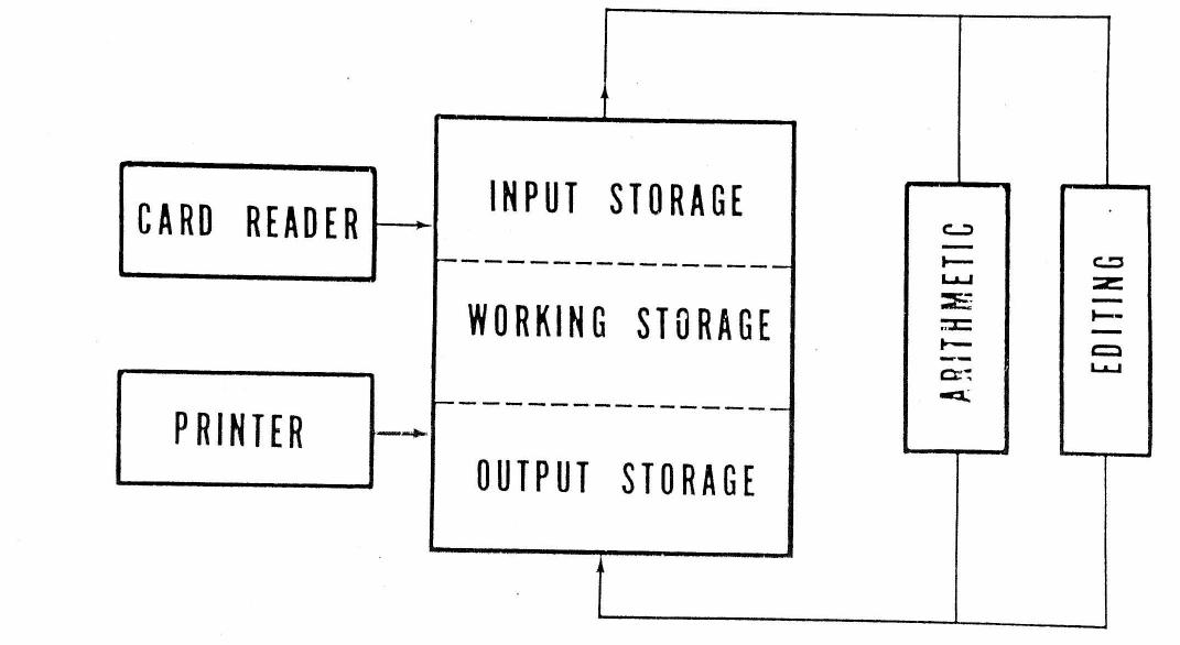 SERIAL EDITING AND SERIAL ARITHMETIC
-3-
Thus, it happens that the card is dumped as is into storage and that the information
in storage is printed as is without suffering any transformation.
Since the information read from cards as well as the information to be printed
is of variable word length, here comes the variable word length concept of the WWAM.
However, in order to simplify storage addressing, this concept has not been
carried to the extent of having a single storage block for the whole machine divided
in characters as the 702 has. The storage has rather been divided in blocks of 80
characters each since this figure represents the length of the most common record,
the card. For printing, either one, one and a half, or two block are used, depending
on the number of print positions: 80, 120 or 160. Thus the card is read into one of
these storage groups and is done in this machine in a unique fashion.
WWAM INPUT MECHANISM
The code used throughout this machine is the well-known 1248 ABC seven bit code.
Conversion from the Hollerith code to this code is required. This conversion
is done in the input mechanism.
The input storage, not like the other storage groups, has two extra rows of
cores. Each of the 2x80 cores in these rows has an additional winding which can
be impulsed from a given brush of the card feed mechanism as can be seen in the
following diagram.
 Cards are read in parallel. Thus when nines are read, the cores in the
two rows are turned on if a hole is detected by their corresponding brush. In other
words, between cycle point 9 and cycle point 8, the two rows of cores hold all the
Cards are read in parallel. Thus when nines are read, the cores in the
two rows are turned on if a hole is detected by their corresponding brush. In other
words, between cycle point 9 and cycle point 8, the two rows of cores hold all the
-4-
nine punchings of the two cards being simultaneously read. While they hold this
information, the storage is scanned and all nines of the card read by the second
set of brushes are sensed, encoded and dumped, one after the other, into storage.
Thus, while the cards are read in parallel, dumping into storage is a serial operation
so that card reading resembles a television image scanning. This system of
reading the card provides the following advantages:
-
The holes of each card can be counted by two little counters
while it is read by the first brushes and then again while it is
read by the second brushes. Thus a read-check is made.
-
The encoder operates in such a way that it permanently gives
the proper C bit for whatever hole is encoded. Multiple punchings
have their C bit adjusted as soon as the second or third
hole is encoded. A redundancy check is thus permanent.
-
All unequal impulses between first and second brushes are
available through the unequal assignment hub for easy starting
of minor, intermediate, and major total programs through
simple wiring as can be seen.
The card columns hubs emit as each column of the card is
scanned. Thus in column 2 an impulse will turn the trigger
on. This same trigger will be turned off when the scanning
arrives at column 6. Therefore, between column 2 and column
6 any eventual unequal pulses will be able to go through the
coincidence circuit and start a minor program.
-
For each different card feed mechanism, a new set of assignment
hubs is provided so that only one set of the card columns
hubs is required even for multiple feed operation.
-
All digit and X impulses are available through a few assignment
hubs for easy pick-up of selectors and other controls.
-
Digit selectors may be used for different columns simultaneously.
-
Brushes are only used for turning a single core each. Poor
reading is either accepted or discarded by the sense amplifiers.
Thus, read-check, selectors and storage get the same calibrated pulses.
This is an important feature of this machine.
ARITHMETIC UNIT OPERATION AND STORAGE ADDRESSING
The WWAM has a serial arithmetic unit but does not have any accumulator.
All information movements are made from storage to storage without going
through an intermediate element. Thus two storage addresses have to be given
at any program step. The WWAM is, therefore, a two address machine. This,
incidentally, solves the annoying problem that a variable word length machine
meets of having to find out the optimum size of the accumulator.
-5-
The address from where the information is read out is called the RO field,
and the address where the information is read into is called the RI field. In an
add operation, for instance, the RO word is added to the contents of the RI
field, and the result is found at the end in an RI field. This type of operation,
we notice, enables us to perform accumulation, the most common operation
encountered in an accounting machine, in a single program step. Accumulation,
in an ordinary calculator, takes three program steps.
Since the storage has only one set of sense amplifiers and one set of inhibition
drivers, only one character can. be processed at a time. Thus the RO
and RI addresses are given alternatively while scanning proceeds so that char
acter, the information can be moved around. A single character register holds
the information from RO time to RI time. In order to perform this, the storage
is arranged so that it can be scanned by two different rings, namely the RO ring
and the RI ring. These rings are alternatively tied to the storage while they are
progressing. This way each ring will scan its corresponding word from low order
to high order.
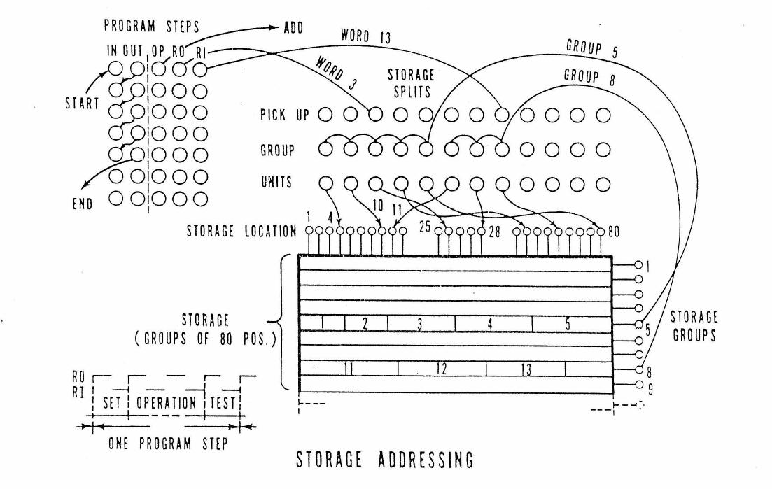
A program step has three different parts as can be seen below; a set time,
an operation time, and a test time. During set time the two rings are set to
the units position of the addresses desired. Each program step has 5 hubs, an
In hub, an Out hub, an Operation hub, an RO hub and an RI hub. The In and Out
hubs are used to establish the proper program sequence. The Operation hub is
wired to the operation add, subtract, etc. required. While a program step is
on, the RO and RI hubs alternatively emit pulses.
-6-
Prior to wiring the program steps, the storage unit has to be split into
words of the proper size. Storage #1, the input storage, obviously is split to
suit the proper card format. Storage splits are used for this purpose. These
have a pickup hub which is normally wired from the program steps RO or RI
hubs, and two exit hubs, one being the Group hub and the other the Units hub.
These two hubs are wired to the storage so that each storage split will define
the units position of a given field in a given group of storage. High order
positions of the words will be fixed by the units position of the word at the
left. Thus contiguous fields have to be defined by contiguous storage splits.
During set time, the two storage splits impulsed by the RO and RI hubs of the
program step will set the two starting addresses in storage. During operation
time of the program step, the storage splits at the left of the ones impulsed
will indicate the ending positions of the scans and thus the end of the program
step. Impulsing a storage split from either the RO or the RI hub of a program
step is, therefore, the same as calling for a word in storage in another machine.
This system of defining the words by wiring the units position is a big
saving in the control panel wiring since it suppresses completely the positioning
wiring required in other machines. Changing of card format or storage distribution
can be done by simply selecting the units plug-wires, as seen on the preceding figure.
Only one selector position per field is required instead of as
many digits as the field has. This is a big saving in selectors. As an example,
a job that today cannot be performed in the 407 because of lack of selectors has
been programmed in the WWAM using only 29 selector positions. An additional
advantage of this type of variable word length over the 705 system is that the
same storage portion can be simultaneously split into several arrangements for
detail and block transfer. This is done by using different storage splits, splitting
the same storage group.
THE PRINT EDIT FUNCTION
This system of storage handling has greatly facilitated the print edit
function. Print edit is essentially transferring information from card storage
and working storage into print storage and simultaneously arranging it in order
to build up a line with all details so that it can be dumped as is into the printer.
Editing even a full 160 character line usually takes only one single program step.
If the line is over 80 characters, two groups of storage are used. These two
groups can be coupled and considered as a single group so that editing can still
be performed in a single program step. This program step calls as operation,
Print Edit, and as RI field, the width of the line. The RO hub impulses through
a storage split. the units of the first field to be transferred to print storage. The
print edit instruction renders operative a row of up to 160 print edit. exit hubs, one
per print storage position. While each position of the RI field is scanned, the
corresponding print edit exit hub emits an impulse. This impulse can be used
to modify the otherwise standard transfer of information from a position of the
RO field to this particular position of print storage. As we can see, in the following
diagram in position 7: the transfer is modified by giving an instruction
"Sign Detect."
-7-
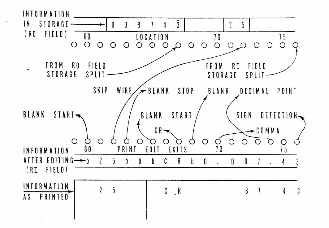 This will detect any sign in top of the character transferred and suppress
it so that a numeric character is printed instead of an alphabetic combination.
Also, the sign is stored in a trigger. At position 74 the instruction given is
"decimal point. " This holds the RO field and inserts a decimal point, then it
proceeds. At position 70 a comma is inserted. At position 68 a blank is inserted.
Then at position 67 the instruction given is "insert CR. " Of course, this symbol
will only be inserted if previously a minus sign has been detected. In case of a
positive sign, blanks are inserted instead. Then the print edit starts inserting
blanks and further along stops the insertion of blanks. In the meantime, the RO
field has been held at a standstill.
At position 62 the instruction given is "skip to position 72. " This will
reset the RO ring which was standing on position 61 and set it at position 72.
Thus the 25 standing in position 72 and 71 will be transferred to print storage.
This type of print edit instruction enables the machine to get information from
anywhere in storage and permits any kind of information arrangement. A similar
operation goes on until the RI field is finished.
A complete set of print edit instructions are available so that any detail
of a line can be prepared. Any character can be inserted and thus fixed words
can be built. It can be seen that zero suppression takes place automatically at
the right of any blank, This is performed through an automatic left to right scan
at the print storage which takes place before printing. No wiring is required
for normal zero suppression. Special zero suppression instructions, however,
are available for treating exceptions. Another interesting print edit instruction
provides the floating dollar sign to protect checks. One single wire gives this
instruction.
This will detect any sign in top of the character transferred and suppress
it so that a numeric character is printed instead of an alphabetic combination.
Also, the sign is stored in a trigger. At position 74 the instruction given is
"decimal point. " This holds the RO field and inserts a decimal point, then it
proceeds. At position 70 a comma is inserted. At position 68 a blank is inserted.
Then at position 67 the instruction given is "insert CR. " Of course, this symbol
will only be inserted if previously a minus sign has been detected. In case of a
positive sign, blanks are inserted instead. Then the print edit starts inserting
blanks and further along stops the insertion of blanks. In the meantime, the RO
field has been held at a standstill.
At position 62 the instruction given is "skip to position 72. " This will
reset the RO ring which was standing on position 61 and set it at position 72.
Thus the 25 standing in position 72 and 71 will be transferred to print storage.
This type of print edit instruction enables the machine to get information from
anywhere in storage and permits any kind of information arrangement. A similar
operation goes on until the RI field is finished.
A complete set of print edit instructions are available so that any detail
of a line can be prepared. Any character can be inserted and thus fixed words
can be built. It can be seen that zero suppression takes place automatically at
the right of any blank, This is performed through an automatic left to right scan
at the print storage which takes place before printing. No wiring is required
for normal zero suppression. Special zero suppression instructions, however,
are available for treating exceptions. Another interesting print edit instruction
provides the floating dollar sign to protect checks. One single wire gives this
instruction.
-8-
As can be seen, the print edit function is a serial operation since only one
operation is made at one time. Only the exceptions require wiring. Normal
word transfer is automatic.
As in the storage splitting, all print edit wiring can be selected to change
the editing from line to line. Here also the savings in selection are enormous.
For summary punching, a similar edit function is provided so that, usually, no
control panel is required in that machine. The same is true for the reader punch.
SELECTOR OPERATION
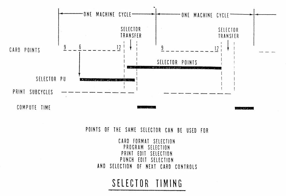
We can see in the next diagram a timing chart where we show the relationship
between card cycles, print cycles, and compute time for an unbuffered machine.
We can observe there that a selector picked up through a punching in a card is up
while this card is computed and remains up until the next card has been read.
Thus, points of the same selector can be used for selecting anything in the machine
and therefore only one type of selector is required.
 In a buffered machine the same timing remains and a control panel wired
for an unbuffered machine can be used without modification in a buffered machine.
THE WWAM SYSTEM
We can see in the block diagram following that the WWAM system is a modular
system. The card readers usually go at the same speed as the printer but
a tabulation speed of 300 CPM is also provided.
In a buffered machine the same timing remains and a control panel wired
for an unbuffered machine can be used without modification in a buffered machine.
THE WWAM SYSTEM
We can see in the block diagram following that the WWAM system is a modular
system. The card readers usually go at the same speed as the printer but
a tabulation speed of 300 CPM is also provided.
-9-
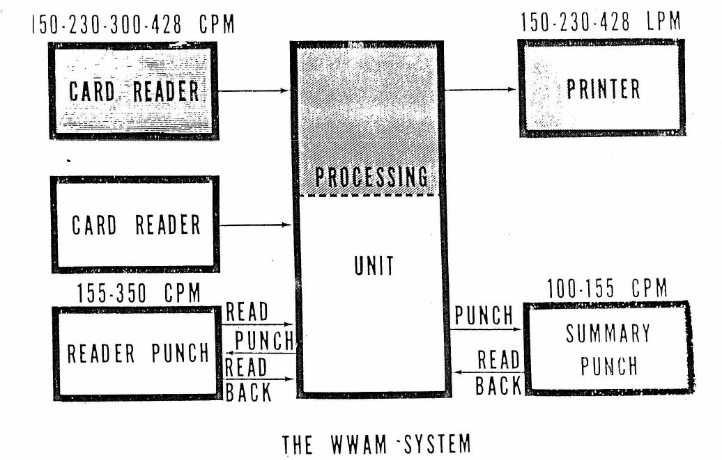 Reader punches of two different speeds may be hooked to the system. There
is provision for reading a card, punching results into this card, and then reading
back the whole card for recomputation. Two different types of summary punches
also may be attached, the ones now in the field at 100 CPM, or a more modern one
at 155. Higher speeds for the Summary Punch do not seem to be too interesting.
The Summary Punch can also read back. Summary punching, as well as all other
inputs and outputs, may overlap or non-overlap computation. Only the shaded portion
of the figure constitutes the basic machine.
Input clutch control in multiple feed operation is done by crossfeed comparing
through an internal automatic sequence. Comparing fields are defined by using
standard storage splits. A basic set up circuitry like the one in the collators is
provided for simplifying the use of the results of comparison. Card feeds may have
multiple stackers. The processing unit may contain multiplication and division,
up to 1900 position, of working storage, 160 program steps and also sterling computation.
All instructions to this multi-unit system are given through a single
407 control panel in the main frame. The fact. that this is possible shows how the
wiring can be reduced using this system. Wiring of this control panel can be done
through the intermediate use of planning charts as in a stored program machine.
CONCLUSIONS
The mechanical units of this machine are now being engineered in Germany
using as basis the work previously done in Poughkeepsie for the stick printer and
in Endicott for the card feeds and paper carriages. Responsibility for the logic
falls on the French Laboratory. Packaging and transistor circuitry now in development
in the United States will be used in the main frame. Thus this machine is
not only a World Wide Accounting Machine in the sense of being usable by customers
all over the world, and in being a universal machine, but also in the sense of the
world wide team that is building it.
Reader punches of two different speeds may be hooked to the system. There
is provision for reading a card, punching results into this card, and then reading
back the whole card for recomputation. Two different types of summary punches
also may be attached, the ones now in the field at 100 CPM, or a more modern one
at 155. Higher speeds for the Summary Punch do not seem to be too interesting.
The Summary Punch can also read back. Summary punching, as well as all other
inputs and outputs, may overlap or non-overlap computation. Only the shaded portion
of the figure constitutes the basic machine.
Input clutch control in multiple feed operation is done by crossfeed comparing
through an internal automatic sequence. Comparing fields are defined by using
standard storage splits. A basic set up circuitry like the one in the collators is
provided for simplifying the use of the results of comparison. Card feeds may have
multiple stackers. The processing unit may contain multiplication and division,
up to 1900 position, of working storage, 160 program steps and also sterling computation.
All instructions to this multi-unit system are given through a single
407 control panel in the main frame. The fact. that this is possible shows how the
wiring can be reduced using this system. Wiring of this control panel can be done
through the intermediate use of planning charts as in a stored program machine.
CONCLUSIONS
The mechanical units of this machine are now being engineered in Germany
using as basis the work previously done in Poughkeepsie for the stick printer and
in Endicott for the card feeds and paper carriages. Responsibility for the logic
falls on the French Laboratory. Packaging and transistor circuitry now in development
in the United States will be used in the main frame. Thus this machine is
not only a World Wide Accounting Machine in the sense of being usable by customers
all over the world, and in being a universal machine, but also in the sense of the
world wide team that is building it.
-10-