Schedule June 2007
return to main 1401 Restoration Page
go to Team Bios
Contents:
Wed June 06 - general
Sat June 09 - - 2nd Sat. - Volunteer Day
Wed June 13 - general
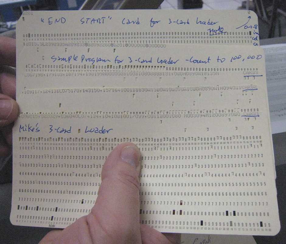
- June 11, added 3-Card 1401 Loader by Mike Cheponis - to aid hand
keypunching object decks. (until we can punch decks from an assembler)
PostScript: I got to talking with Ron Williams about quirks of the 1401 processor.
We got to talking about power up sequencing of the 1401. If there is a problem,
such as an open interlock or bad relay contact, you can have a very interesting time blundering about.
Oh yes, the current list of power voltages in the 1401, 1402, 1403 is
About 729 tape drives, from Van Gardner
The fact that this appears to only happen if reading the card takes enough time that the go line to the tape unit is dropped then raised may be a clue that the prolay is not getting the tape up to full speed before writing starts. If this happens the characters will be too close together on tape. This can be caused by too large a go gap between the prolay idler and drive capstan on the right side.
Another cause is the left side prolay "glitching" caused by overthrow when the arm moves from the stop capstan to the neutral position. If the left side idler to capstan gap is too close or there is too much slop in the idler, arm and armature pivots it will momentarily go past neutral and hit the drive capstan slowing the tape.
When you worked on prolay machines all the time you could walk into a room and recognize the "clacking" sound when they were glitching. I used to demonstrate this to CEs in field schools I was teaching by setting the off-line tester to read an all bits tape with a short go down time. Then I would move the left prolay closer to the drive capstan until we could hear the glitching. Looking at the preamp output on a scope you could see the dip in the start waveform caused by this.
It's going to be hard to get the system up to error free performance with the lack of parts. We used an enormous amount of prolay nylon idlers and their shafts. The original idlers were white nylon that was almost translucent, then a solid white, then black. In a shop that ran 24/7 they would get a grove worn by the tape along with bushing wear. The idler shaft, arm shaft and armature shaft are probably standard drill rod sizes that can be bought at an industrial supply house.
Before the navy I was a machinist that made parts for sock knitting machines and I used to order it all the time. Now I have gone to rambling again.
One of the best things you can do to help the TAU debugging is to get a second 729 working. That's the best way to tell if the trouble is in the TAU.
Van Gardner
Sat June 16 - Grant's card testing proposal
We can combine all three approaches into one plan:
I would suggest testing each card during the cleaning/inspection removal
process, or removing cards of the same type in a bay and replacing them
with known good, tested cards as a way to maximize up time for overall
system margin testing. In many cases we have enough spares to do this on
at least on a partial by bay approach. So the challenge is to have
known good cards and that requires volume testing. Finding some more
spare SMS cards is also desirable where we have few or none (50% of card
types).
With the conclusion of each round of module testing, inspection, and
cleaning, run the machine diagnostics and use the margin test supply. I
tested the portable margin power supply with negative results and
concluded that its design needs to be documented as the test conditions
I used may have not been appropriate (load resistor only). Assuming we
gain confidence in this supply we still only have the ability to test
the entire machine under margin which I think may be unproductive (too
many simultaneous bugs to shoot, but this assumption is easy to test by
testing the whole machine under margins). I inspected the power
terminal blocks for each gate and I think it is feasible to install a
reversible modification (plug) that would allow margining by gate.
I have been considering different designs for an SMS card tester and
have settled on the following ideas:
After considering a number of tester design alternatives, I've rejected
the following:
In other words, I propose build simple testers that most any engineer
can understand, use, and fix. Never have to worry about the next
release of Windows.
What I think might work as an approach is as follows:
The tester build and card test priority is by two sorts:
I would make each tester complete with it's own self contained +12, +6,
-6, -12 and both margin supplies with high, nominal, and low outputs.
This is a little more work but yields redundancy of test capacity.
Volume card testing can commence as soon as the first tester is built.
A 4 bit synchronous counter and a few gates can produce the necessary
logic test signals. All of the trigger inputs and states (and set up
times met) can be tested with 4 bits. Most of the gates are 4 or less
inputs (plus expander) wide and back to my idea of a plug crossbar, a 25
pin or so connector can personalize the gate testers for each card type.
(test signals to inputs plus loads as needed).
One part of the design still pending is the level shifters from 74HC to
logic family. I'm partial to using high speed video/op amps because:
The double width card test box that I made is the mechanical model, but
it only needs to be one card connector wide. I've got most of the parts
(connectors, voltage regulators, logic, boxes) to build 3 or 4 testers.
The hot/cold temperature chamber is a Peltier device with heat sinks and
mini muffin fans both sides in back to back recirculating chambers. The
bottom is open so either hot or cold air can be circulated over the card
under test. A variable current source controls the temperature
differentials.
A next step would be to debate these ideas, get a team together to
design & build card testers, and to develop a plan for cycling
inspected, cleaned and tested cards through the machine. I'm out of
cycles to finish the design and build testers on my own. My shop is
available to the team.
Regards,
Grant
Tue June 19 - cleaning
The rest of the photos are in http://web.1401.org/Module_B/Gate_1/1401__Module_B__Gate_1__Row_F.zip - This file is 76 MB so I didn't want to attach it to email.
I've also included in that .zip file a .txt file with the card types for that row.
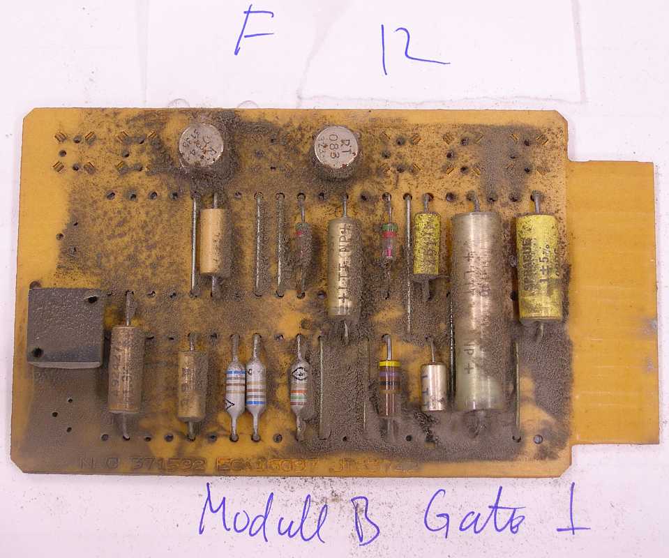
It's interesting looking at these. Card 5, type KA, has that burnt-looking resistor; I could not find an identical type KA card in the spares, so I did not replace this card.
Card 25, type QC, has 2 power transistors that had a piece of insulation glued on top of the TO-3 cases, presumably to prevent it shorting out the adjacent card (or maybe for thermal?). Anyway, the one remaining dark disc of insulation fell off the transistor, and so, insulation must be placed on this card, on both transistors!!!
I re-installed this card without insulators (I did not have any insulating material handy) so that I could test the machine. There is clearance, but I think either this card should be replaced or some sort of insulator needs to be installed on this card.
----------------------------------
I plan on cleaning the rest of the rows in this gate, then moving to another of the 8 gates in Module B (the lower "quadrant", just below the 1401 control panel; Gates 1-4 are in the front, and 5-8 are in the back.)
Then perhaps to Module A, the one on top, and then to the modules on the right, modules C and D.
It took 2 hours to remove, photograph, clean, vacuum, dexoit on contacts, and deoxit gold on gold contacts for these 23 boards (and another hour to tweak-up the photos) .
Therefore, if the rest of the modules are similarly fully-loaded with cards (and I know they're not), the total number of rows in the machine is: 6 rows per gate x 8 gates per module x 4 modules = 192 rows of cards, meaning it will take 384 hours to clean the CPU box. If we figure I can get it down to 1.5 hours per row, and that about a module's worth of power supplies exists, then that's around 220 hours.
At 4 hours per week devoted to this task, it'll take about a year to finish; and the work really needs to be done when others aren't using the machine.
-Mike
Wed June 20 - general
P.S. Frank King says that a CHM contract van and mover(s) will be at Werner's in Portland, OR July 20th.
He is a little busy around then and prefers some other 1401 expert to help select materials not currently
inventoried (like buried in the piles) for transportation to CHM and the 1401 Restoration effort.
Thurs June 20 - tapes
We determined that the I/O channel terminator shoe that has black tape wrapped on its cam lever is intermittent. The drive select operations worked fine using the other terminators.
We found a broken ground wire in the 729 read amplifier gate. It didn't seem to be related to any known problem symptoms.
I believe that we are having tape drive port select relay problems again. The 729 we are using has a dual port feature. When we access the drive from port "A", the C-bit in data bytes get dropped.
The tape diagnostics like still 5040 act as a good demo. The card reader reads, the tape spins, and the printer prints (a lot of error messages). Maybe we should leave these dropped bit bugs on the machine, if we fixed them running the deck would be less interesting. ;^)
I'll contact Andy and see if he wants to and can help.
Regards,
Sat June 23 - 4th Sat
There were frequent reader checks and punch checks, but the final result was OK -
Wed June 27 - general
Also Tuesday night, K. Bleher (of HzG in Sindelfingen) the e-mailed 1401 ALDs 42.67.01.2
and 42.67.02.2. Much appreciated !!! :-))) Thank You Very Much !!
Later, Allen Palmer sent the following
I fixed the problems with reading from the tape. Both problem were physical
problems within the channel switching relays
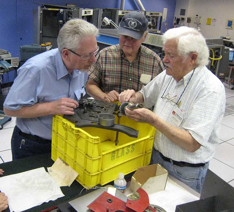
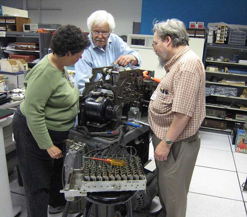
This reassembly is somewhat like re-assembling a watch - you don't want to leave too many parts out. Most of 'em
probably do something. ;-)) Maybe it is more like re-assembling a gasoline engine in that various parts
must do things at particular times - for instance you don't want the valves open on the compression stroke, nor the
spark during the intake stroke.
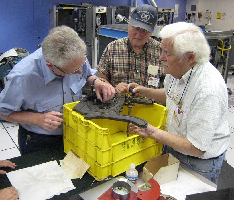
Lets say that you re-assemble the 513 incorrectly or out of time
A little less lucky, and the machine will jam on hand turning, and you will enjoy dis-assembling
it again for another try.
And I am told that there are a number of ways to mis-assemble the machine that will break things when powered up.
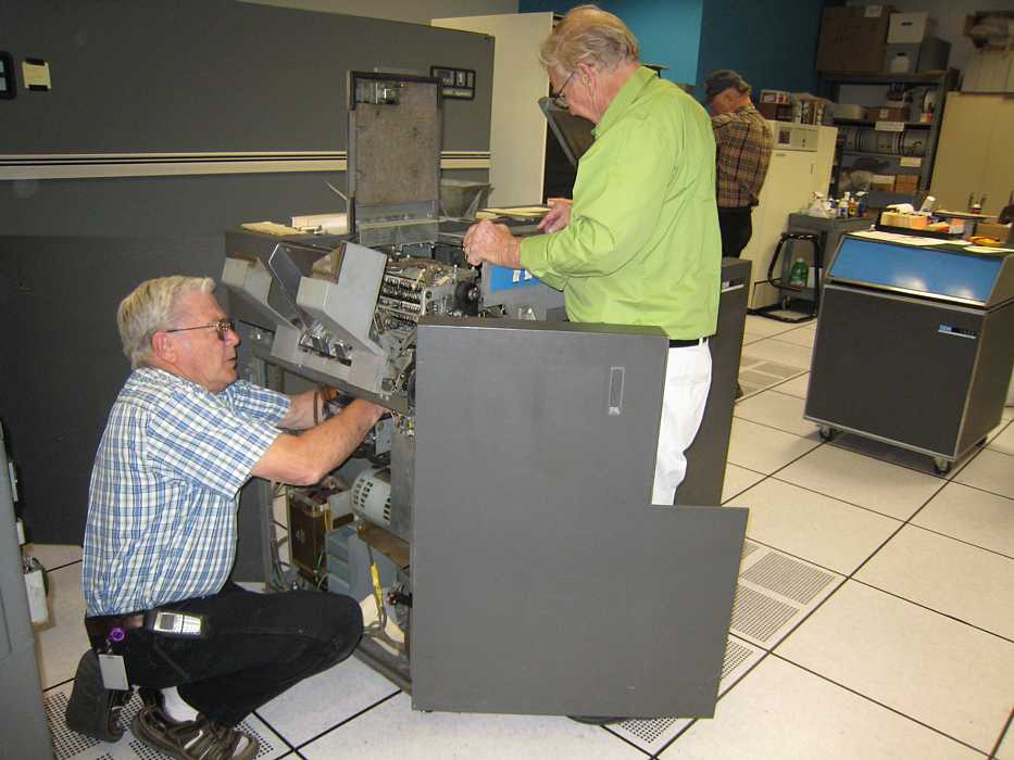
Here is Bob Erickson re-checking the alignment for Judith Haemmerle and Ed Thelen to photograph.
So - this is the first cut of the inside the crank case timing - and there is timing on the outside the crankcase
timing that has to be right also. Oh yes, there is an electrical distribution thing on the other side of the
513.
Dan McInnis dropped by, and found the tape drive working, but didn't have his Demo Test Deck in his pocket.
He promised to give his new software a trial spin next time.
Ed Thelen is patching his Big Print (Banner) deck so that multiple customers can be printed up in
one run (as opposed to one customer per run).
Wed June 06 - general,
Sat June 09 - 2nd Sat. - Volunteer Day
Wed June 13 - general, About 729 tape drives, from Van Gardner,
Grant's card testing proposal
Tue June 19 - cleaning,
Wed June 20 - general,
Thurs June 20 - tapes,
Sat June 23 - 4th Sat.
Wed June 27 - general,
This report is via Ron Williams. Ed Thelen was AWOL, at the Allen Telescope Array in northern California.
- the existing logic seems to make correct logic levels
- false A-reg errors,
- Accessing upper memory from a program in lower memory
works in run mode, won't work in single cycle -
"Sinister stuff"
- power up won't load, tape runs tape off end of reel,
- capstan motor doesn't retract, ...
Lunch with out Robert's bagels was just fine -
Ron says that Allen sniffs out food. Allen found the remains of a breakfast event at CHM.
"... bunch of left over fruit, cup cakes, healthy stuff, mellons, pineapples - he sniffes it out"
Swapping back the relay seemed to help - in any case we now have two good working
026 keypunches again. Dan used one, and I used the other to make patches to change the
operation of the Big Print - Banner customer demo ;-))
Then when Dan McInnis came in to keypunch his object deck, we found that Salim's keypunch didn't work.
Bob Erickson found a relay (related to punching alpha (not numbers) was getting very hot.
Then he found a relay that had been swapped out of the 3rd 026 keypunch (with out a note or a tag -
naughty naughty).
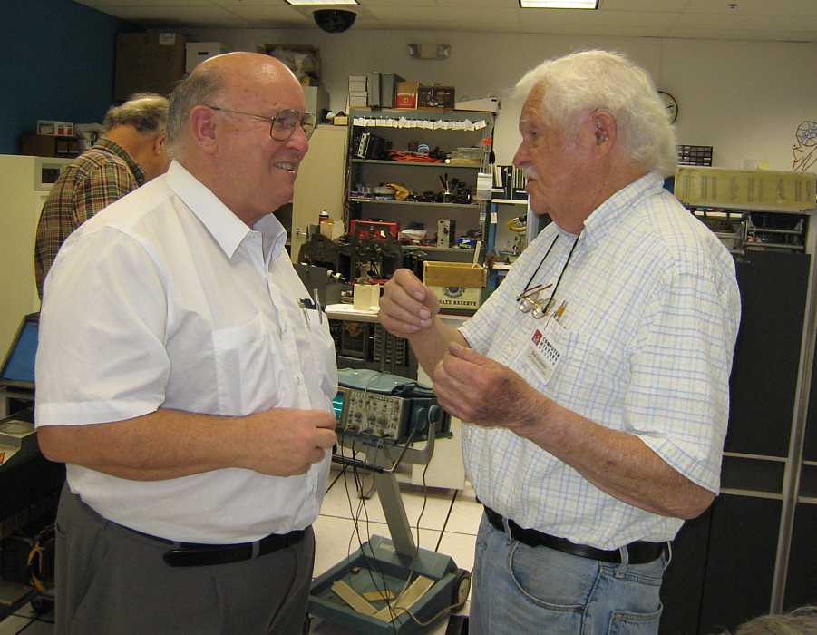
Grant Saviers came by and had an extensive conversation with Bob Erickson.


William Caulli (Brisbane, Australia) came in and said that he was involved with a similar 1401 configuration
as ours except they had 6 tape drives and only 12,000 characters of memory. He was quite excited about seeing
our system and seemed *very* conversant with many details of hardware and software.
He started talking about code breaking with the aid of a 036 sorter with a count printer attached.
Soon he and Bob Erickson were talking about the breaking of the Japanese code called J26 using IBM unit record equipment.
Mr. Caulli seems involved with the
MacArthur Museum Brisbane, especially the upcoming code breaking section.
We made a Banner printout with his name.
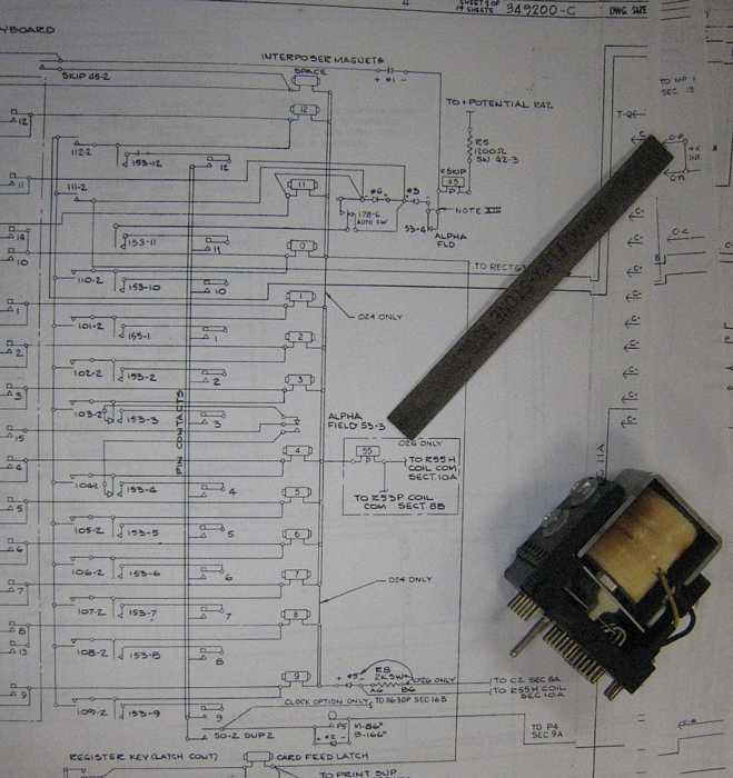
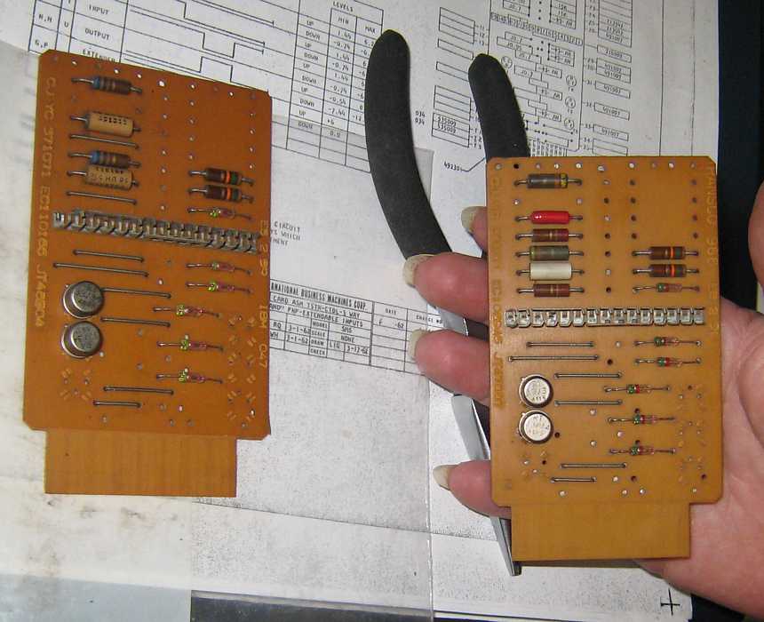
Tim Coslet said the left board was made by IBM and the
right board by Transco. They are different - two resistors in the upper left quadrant are replaced by wires.
The total resistance is 680 ohms on IBM board and 250 ohms on the Transco board.
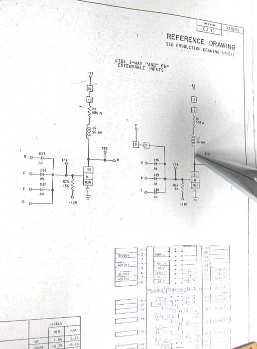
Schematic of the board
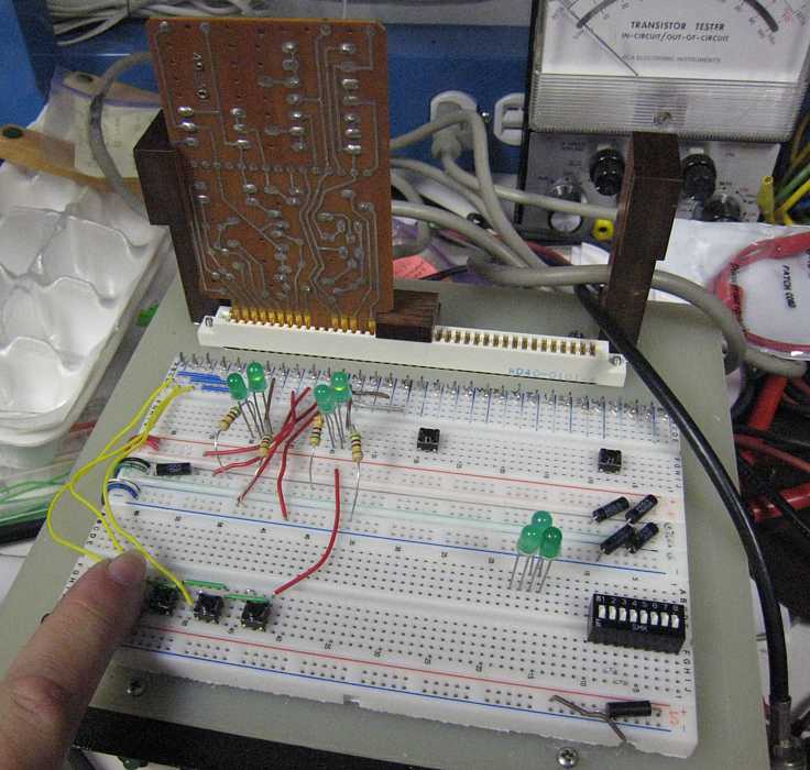
Test jig showing both circuits working well on the IBM board. The Transco board was in spec, but did not light the second light.
- June 11th, 083 Sorter status from Frank King. "Ed, right now I am missing feed knives. Trying to locate one set and
waiting for machining on another. After I get a good set I still have a
jamming problem in the chute blade pocket selection area."
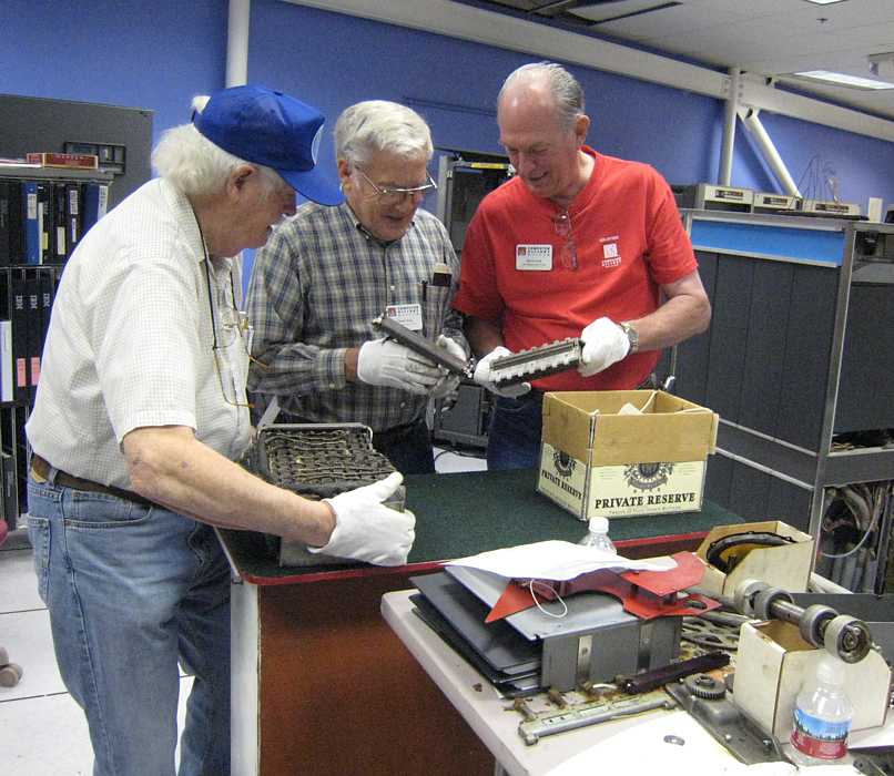
Mike Cheponis and Grant Saviers came in about 2:30
Alex Bochannek signed a request form to obtain parts from Visible Storage to repair the 513 reproducing punch.
(The unit had been received with serious damage to columns 72 - 80.) Here are the results of the raid :-))
About the white gloves. I think it was humor - in our greasy environment they are almost never used.
Maybe the bandits did not want to leave fingerprints - for many reasons.
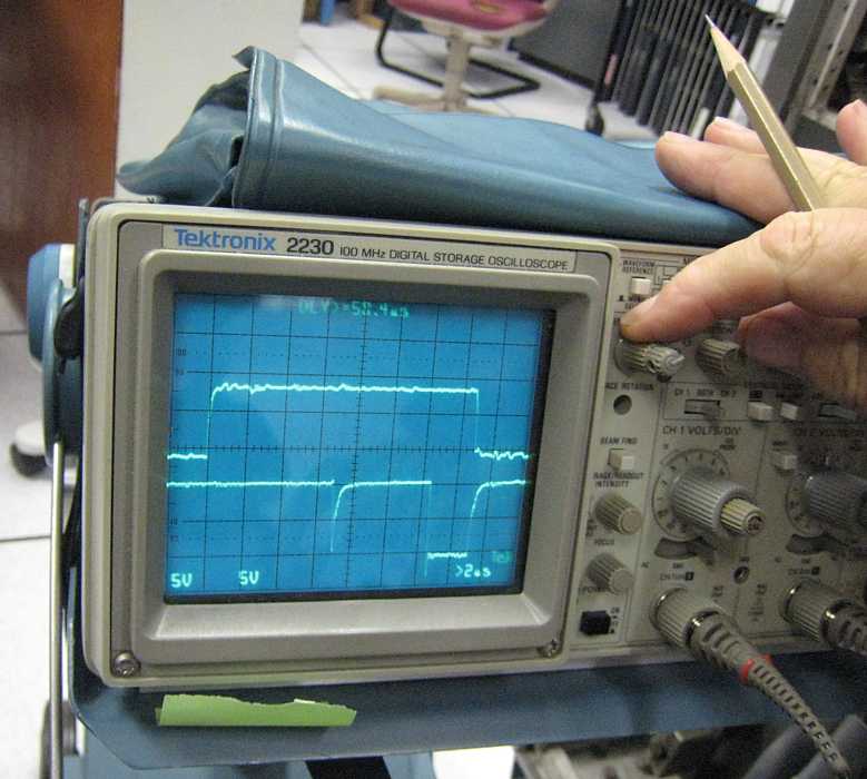
Ron Williams is chasing the source of this short improper pulse. Could it be causing our remaining 1401 quirks??
Later, Mike Cheponis sent "Ron showed me this - we put a 10 nf to ground on this pin, and this brought up
the glitch to -3 volts, and a little bit smeared the trailing edge of the pulse. But the program still
had the same incorrect behavior. (That is, the glitch does not seem to be causing the incorrect behavior.)"
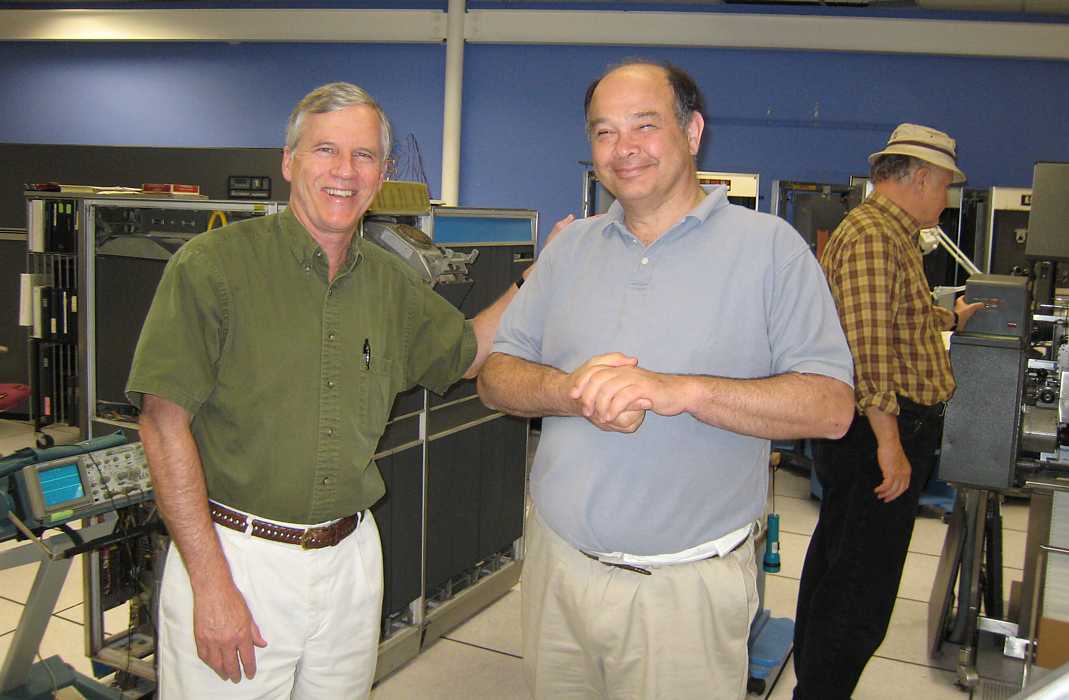
Robert Garner and guest Peter Capek have known each other at IBM for many years.
Frank King noticed black dust on the floor on the cable side of the 1403 printer. What is going on?
Is this indicating a problem??

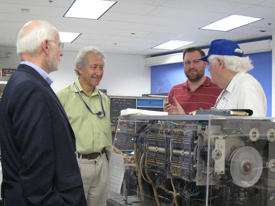
(Left to right) Prof. Michael Mahoney, Princeton University, Doron Swade, and Alex Bochannek and Bob Erickson talking over the plastic enclosed 077 collator.
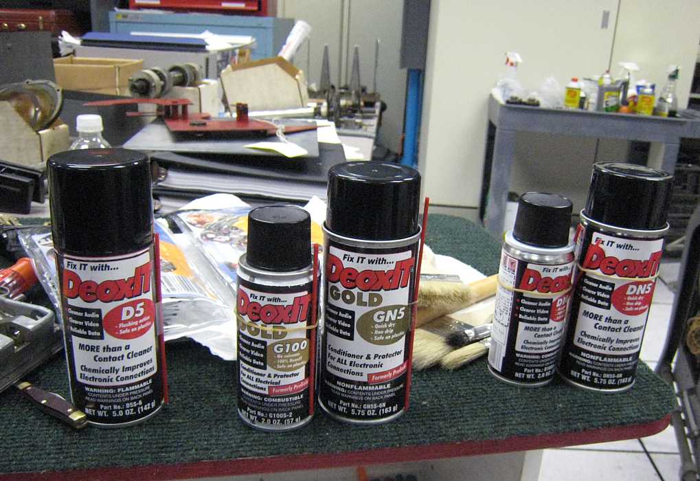
Mike Cheponis brought in these DeoxIT products which he says do a very good job in cleaning troublesome situations.
(I tried to tease him that he is trying to de-toxify us - but Mike remained serious. :-|
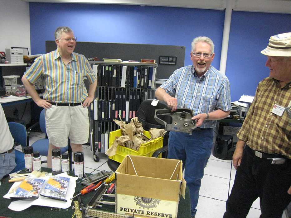
Grant Saviers brought in a big box of 513 reproducing punch parts he had worked on. Two smiling Santa Clauses. :-))
Probably the most "interesting" is that the SMS family, among other things has two sets of logic levels
- "U" logic which swings 0 volts to -12. The PNP transistor emitters being at 0 volts
- "T" logic which swings +6 to -6 volts.
The 1401 TAU (Tape Adaptor Unit), has many different cards than the rest of the 1401.
I think a good introduction to 1401 trouble shooting would be a study of the power up sequence.
Ron was introduced to the 1401 that way, and I was introduced to Nike fire control and the GE 225 that way
as well.
- 12, -6, +6, +12, +20 (memory core drive), +30 (memory logic), +60 (1403 hammer drivers)
The 729 tape drive power voltages are different yet :-))
On the subject of the Card to Tape diagnostic getting tape errors.
,
On Saturday June 16th, Grant Saviers sent the following:
I think the goal of substantially increasing the reliability of the
machine ought to be our first priority, and encourage us to develop some
plans to do this. Cleaning and checking cards is one approach. Another
is to use the margin capability in the machine to isolate marginal
circuits. Thoroughly testing most SMS cards and weeding out the weak
semiconductors is a third.
- A trigger/latch/flip flop tester
- A gate tester
- Higher performance gates and registers/triggers first
- Quantity of card type in the machine
From Mike Cheponis
I cleaned, vacuumed, and deoxit Row F of Module B, Gate 1 this evening. Machine still seemed to work when I was done, so I probably didn't break anything.
Attached is a photo of a typical card as removed before cleaning.
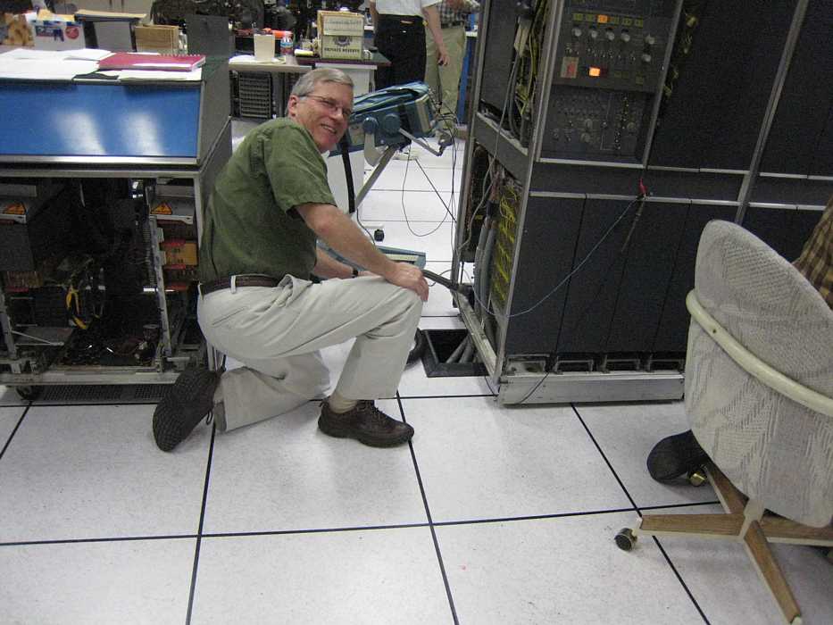
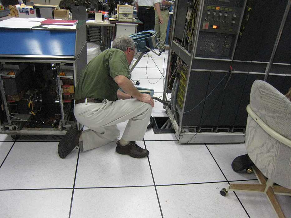
We got started right!! Robert Garner is on his knees vacuuming some dust/dirt/grime deposited during the
SMS card cleaning Tuesday. Robert really wanted to appear a little more photogenic,
but I also caught him hard at "work" ;-)) (Robert really tries to keep a tidy ship.)
Any part of memory can now be accessed by a program in any part of memory with out machine check and
corruption of memory. :-))
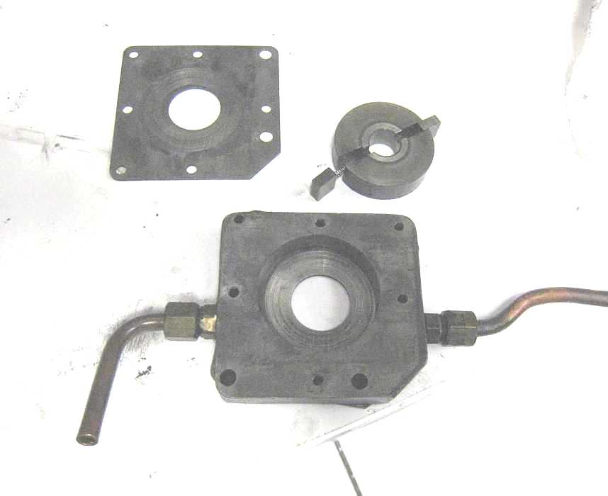
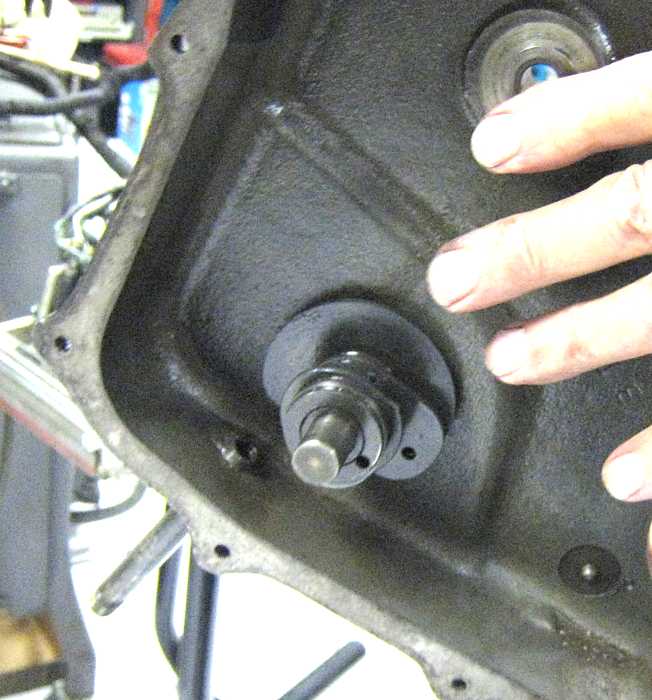
Bob Erickson and Frank King worked all day on the 513 reproducing punch. Here is the warn oil pump.
Note the scoring in the rotor chamber and on the face plate. The roter (operated in an eccentric mode,
like a Wankle engine) seems fine. The two wipers and their springs seem just fine also. Frank was proposing
to flip the scored faceplate over, use a flat grind stone to flatten it, and use the "new" side. I don't
know the final result.
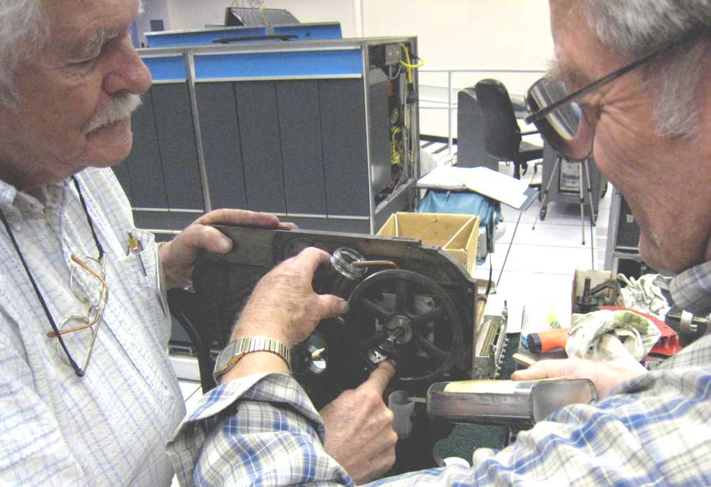
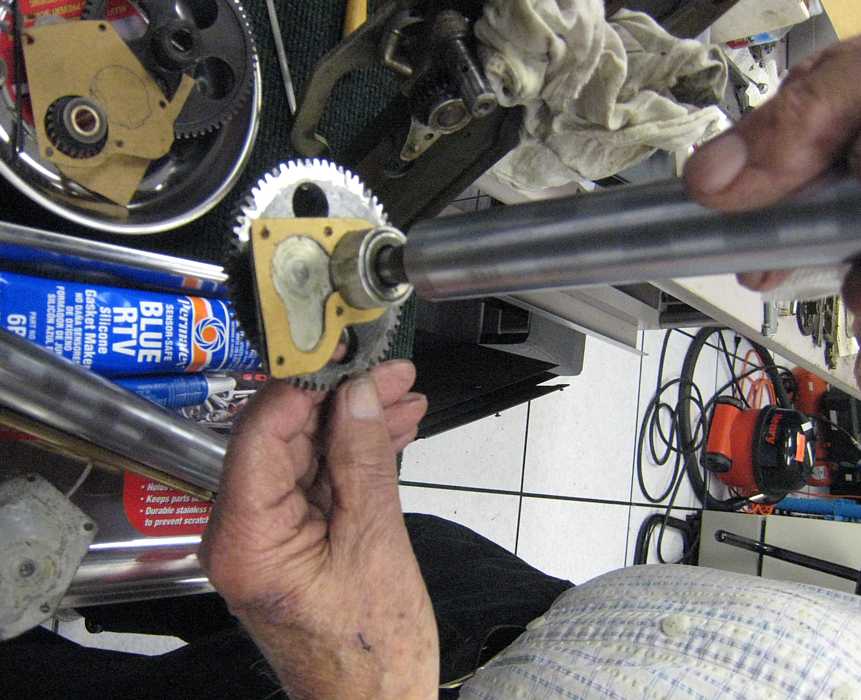
Here it the refreshed? reassembled oil pump under test. Bob Erickson, left, is turning the gear driving
the pump and Frank King is pouring oil into the pseudo oil sump (a little plastic cup) and holding a catcher bottle.
You can just see some clear fluid coming out of the top copper pipe :-))
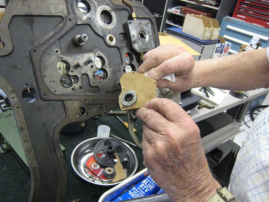
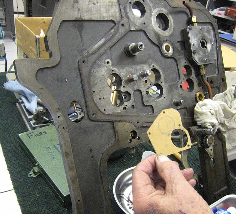
Frank was cutting gasket material
to replace those torn in disassembly or otherwise damaged. Here Bob shows part of the results.
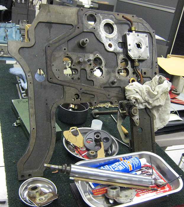
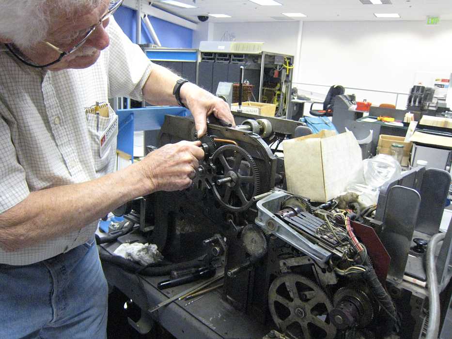
Bob and Frank are getting organized to re-assemble the 513. No small task - not only do all those weird parts
have to be stuffed and crammed back in somehow, but the gears, cams, levers, ... must be "timed" so that
the correct things happen at the correct time in the card punch sequence. Note that the oil pump has been
re-attached, and the scored side of the face plate is indeed facing out.

Bob keeps muttering "one tooth past 14". I worried about his sanity, but this gear and reference point
is what he meant (he says).
And please don't ask why the sequence 9, 13, 14, 12 - maybe the two punch rows between cards are 13 & 14 ?
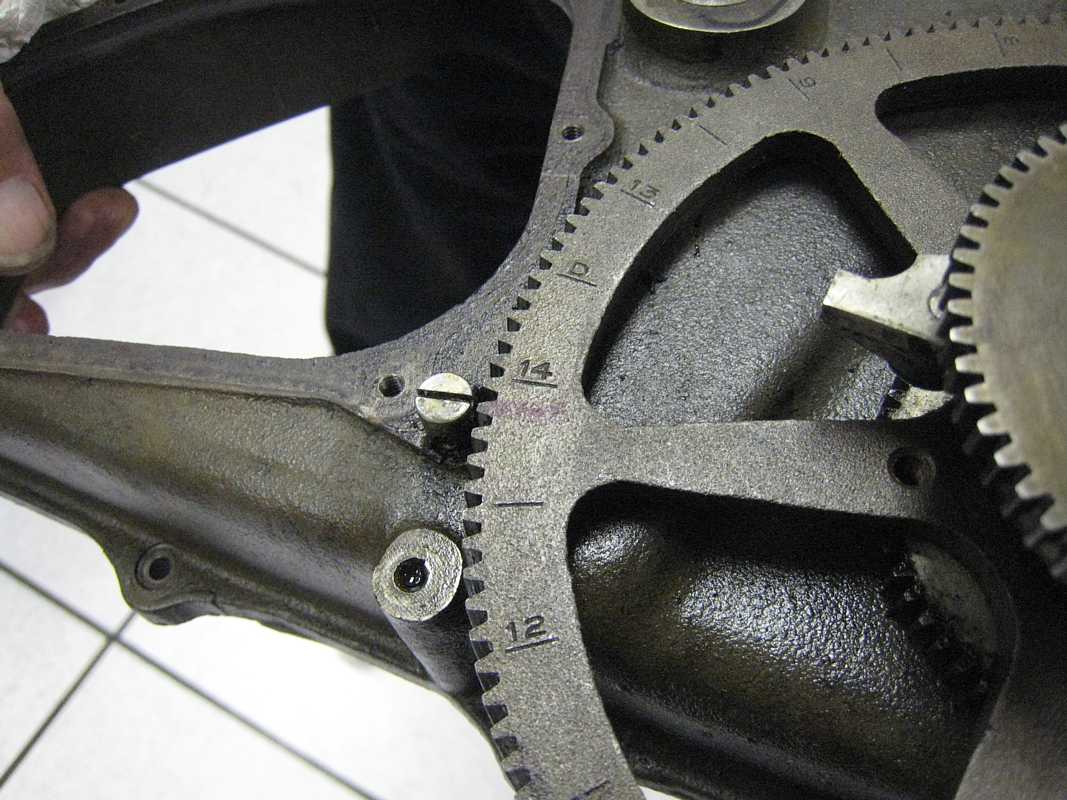
Then you "back off seven teeth" and some levers can slid over these cams with out jamming.
Robert - do you think Joe deserves a gold star and 10% raise??
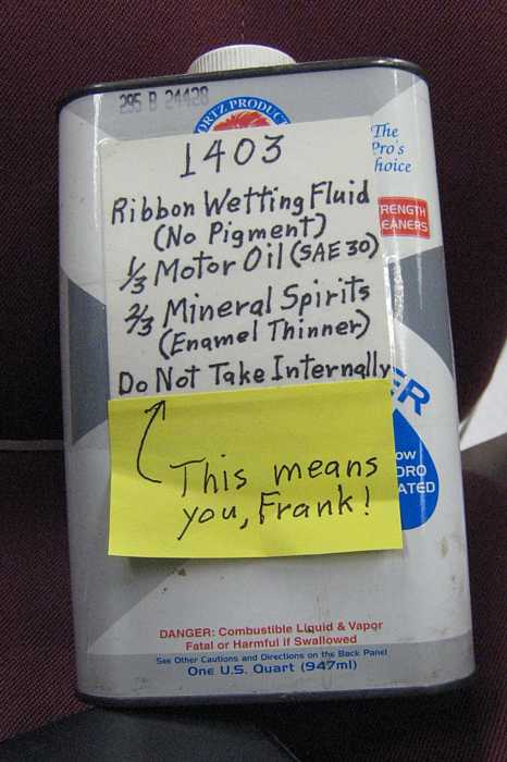
Ron Williams is a dreadful tease. Here is his recipe for refreshing dry printer (and keypunch) ribbons.
I believe he intends for this concoction to be misted onto the moving ribbon.
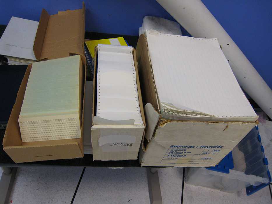
Three folks from the Silicon Valley FORTH Interest Group
came by to see our current state of disrepair. ;-)) They came
bearing gifts - a box of unpunched cards, a box of tape labels, and a box of fan fold printer paper :-))
They wish to remain anonymous :-|
e-mail from Bob Feretich
If a diag deck used to load, but won't now, I'd check the order of the cards in the deck. They may have gotten shuffled. I loaded 5040 today and it read fine.
When we access the drive from port "B", the A-bit in data bytes get dropped between the final read amplifier and the channel cable. There are only wires and the relays in between these points.
Bob
Doron Swade, CHM Guest Curator and force behind getting Babbage's Difference Engine constructed after 150 years,
is lecturing some docents interested in committing to a year demonstrating, cranking, maintaining
a loaner Engine (all 5 tons) for one year.
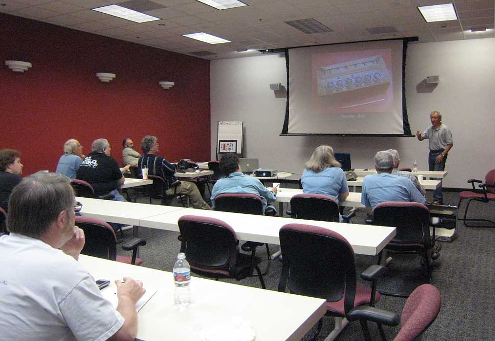
There are slots for 4 maintainers to be trained by the British experts. (I think "they" should set up
bleachers so "the rest of us" can watch ;-)) "They" could probably charge admission ;-))
Judith Haemmerle signed up as a candidate maintainer, having worked on slot machines, pin ball machines,
clocks, and other physical things - but worried that her lack of working on big stuff would hurt her chances
of being selected. I said come to the 1401 room and enjoy working on restoring a 513 reproducing punch.

She seemed to fit right in.
I bet there is no way to guess what these guys are trying to fix.


They are examining the print out of a tape drive test. What can be causing this
type of data garble???? (Blanks are printing as @, everything else seems OK.)
Tim Coslet found that this diode took 1.17 volts to conduct a little, instead of the normal (for germanium)
of 0.3 volts. (Silicon diodes take about 0.7 volts to conduct a little.) This high bias, coupled with
a slow weak circuit driving it, caused a killing delay :-((

AFTER I found out that the 1402 punch cards are loaded 12 edge in !! (The reader side is loaded 9 edge in !!)
The rational for this strange situation seems to be that
both reader and punch cards can go into the center pocket
of the 1402, and this makes that pocket have a reasonable output deck :-|
Tuesday night Bill Flora sent this list of belts. - Certainly not for our little 1401???
Tape drive debug update.
Allen j Palmer
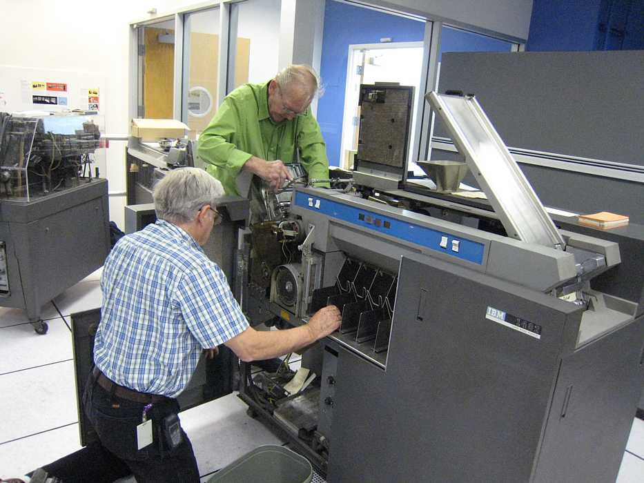
We ran the Big Print demo - and began getting card reader halts, like a mis-feed in the card reader.
It seemed to be the second card of the deck, so we reproduced it on a key punch.
We decided to reproduce the Big Print demo, using the 1402 Card Reader and Card Punch, similar to last Saturday.
Well, the first card in the card punching jammed. OK - Then the fun began - how soon (40 years) we forget.
Bill Flora the 1402 chief wasn't there, and the rest of us looked like the Marx Brothers. I dived into the
back side, and was corrected by the experts that operators were not allowed in the back side, and this
` was only a card jam, and operators routinely cleared jams. But we couldn't get the card die out any other way !!
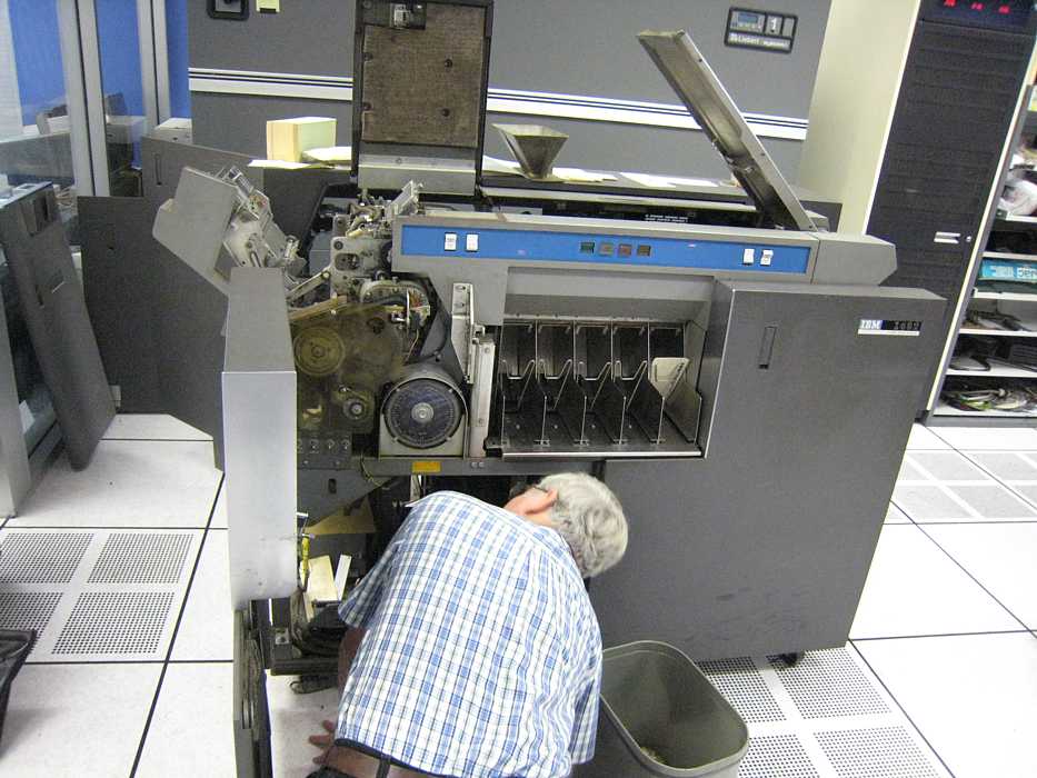
OK, punch die removed, from the back side !! ;-))

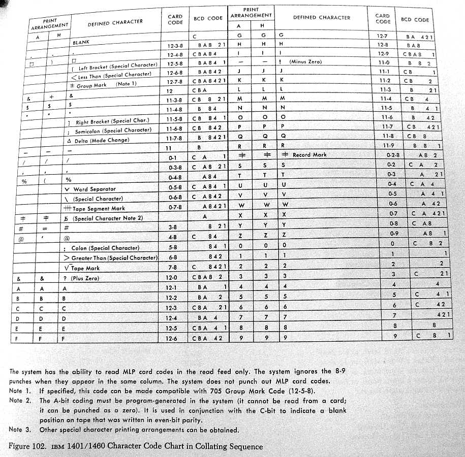
While labeling the working library notebooks, we found a 1401 collating sequence, which seems important.
(File is 160 K Bytes)
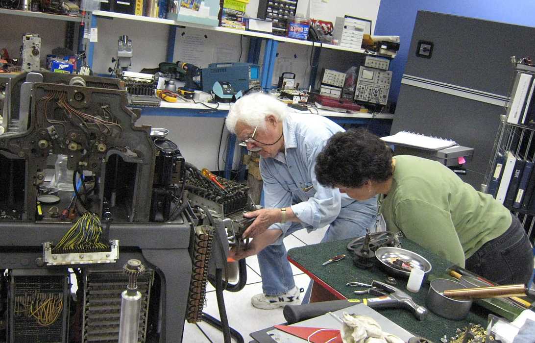
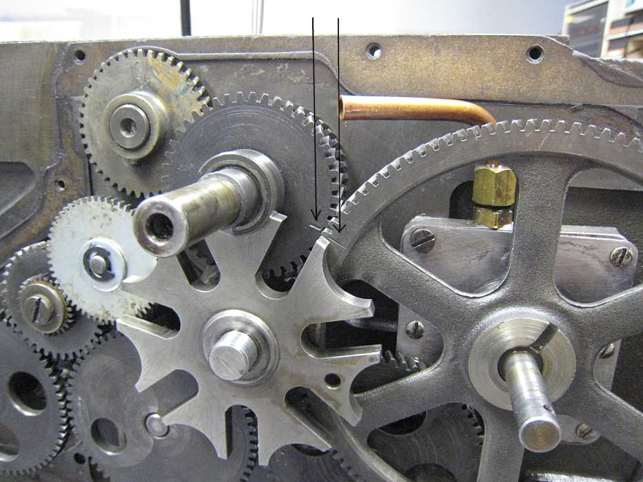
Now the serious stuff!! Bob Erickson is starting to re-assemble the 513 Summary Card Punch - which has
several swapped parts and reworked parts and new gaskets and I don't know what all -
- If you are lucky, you just won't be able to get the parts back in :-))
The 513 manual shows and names the parts, but rather leaves it up to on-the-job training to get the
various parts "timed". Bob Erickson remembers this stuff - and we better get it recorded for the next crew!!
So - first cut - straw man - sacrificial lamb -
Drift Pin - stuck in hole in eccentric behind wall, to be vertical, eccentric at top dead center.
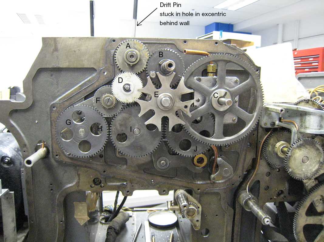
Detail of timing gears (A), (B), (C)

Detail of timing gears (B), (C)
Note the timing marks on (B), (C)
The 1401 halted after reading one text card. OOPS -
forgot to put a word mark into the 1st position of the card read area. Ron Williams said this blunder tested
the wrap-around error halt - OK - one more thing tested, and works.
Ron inserted the word mark and the
text describing the 1401 to be printed later got read into memory just fine, and the date card also.
The program then printed out customer names and today's date in the appropriate "fonts" just fine :-)))
OOPS - I forgot to print out the 1401 text for each customer - next time :-))