Status report of the "Interim" 50-Hz
1401 power delivery situation
(via 3 Elgar 1750 converters), 11/18/04:
by Robert Garner
Thanks to great sleuthing by Ron, Bob, et al, we are (for the time being) commandeering the 24VAC control circuit of the 1402's power distribution main contactor. This results in the power staying up for several minutes with the 1401 and 1402 supplies enabled.
Unfortunately, after 5-15 minutes, the 30A, 208Y/120V, 3-phase wall panel circuit breaker reluctantly trips. What's causing that? At Elgar's suggestion, we captured a scope snapshot of the Elgar input line current for PhaseB:
 Elgar Input Current -
Phase A
Elgar Input Current -
Phase AThis current waveform is measured across a resistor between the two leads of a Fluke C-clamp-on current probe, where 1 mA reading = 1 A in wire. The resistor is 10 ohms, so 1 mV in the plot corresponds to 0.1 A in measured wire, or 200mV = 20A (vertical division in plot).
As the Elgar support engineer, Grady Keeton, expected, the wave shape has narrow peaks and valleys (up to 58A and down to 54A). These are apparently the traits of a "heavily rectified load" representative of linears with diode bridge rectifiers and large filter caps. Note that the scope's computed RMS value is ~25A, which is also precisely what the Fluke RMS meter reports. (Note that a sinusoidal waveform would peak at 35A positive and negative.)
After soldering diagnostic wires suggested by Grady inside the PhA and PhB Elgars, we also measured several internal critical levels, including the pre-amp input (~3Vpp) and its supply rails (+/- 42VDC). They al looked OK and within range. (We did find/replace one bad 50uF/50V electrolytic cap, C106, on the PhA pre-amp board, but didn't seem to make any difference.)
We took measurements of the Elgar input and output RMS currents for the 3 phases with the Fluke meter. On the input side we saw 20A, 25A, 23.5A, for an average of 23A per phase. This corresponds to an apparent building power draw of 3 * 23A * 120V = 8.3 kVA.
The Elgar output/1402-input phase currents, with 1401 & 1402 power supplies on, were measured at 5.5A, 6.2A, and 0.7A, for a total Elgar apparent load power of (5.5+6.2+0.7)A * 220V = 2.7 kVA. So the Elgar input/output power ratio is 8.3/2.7 = 3.1x, which is what Grady expects for this class of converter. So the Elgar's seem to be doing their jobs.
The conclusion is that it's likely that we have a sensitive/defective 30A 3-phase circuit breaker and will need a 60A breaker soon anyway--see following. We'll relay that to the Museum's electrician, Jim Yee.
Grady also pointed out that to determine how much actual power the Elgar can handle, that we need to de-rate it according to this chart from their web site (applicable to linear converters like ours):
 All Phases Nov 13
As our rated Elgar output voltage-to-neutral (as strapped) is 260V and we're running it at 220V, then our "percent of rated output voltage" is 220/260 = 0.85. Assuming our 1401 load power factor were say 0.6 (we should try to measure it), then from the chart, the "percent of rated output VA" is ~0.86. So our max achievable Elgar actual power delivery would be 5.25 kVA * 0.86 = 4.5 kVA.
So we're probably running the Elgar at 2.7/4.5 = 60% capacity right now (with 1401 & 1402 supplies on, but no 1403 or 729 on). We could handle 1403 or one 729, but not both at same time. If/when we reach the max power, the output voltage will/should begin to droop.
A 4.5-kVA 1401 load would correspond to a input draw of 3.1 * 4.5 = 14 kVA. Since a 30A breaker can "only" source 3 * 30 * 120 = 10.8 kVA, close to our 8.3 kVA draw, we need a 60A breaker (21.6 kVA) when we reach our max Elgar draw of 14 kVA (soon!).
Grady discussed types of circuit breakers (thermal, magnetic, combination), and it's possible that a magnetic circuit breaker would be a better match. (and possibly even a "delayed breaker" so we could turn on all 3 Elgar's at once without tripping wall breaker.).
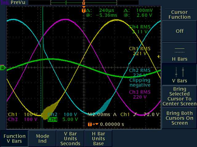
The "other" power challenge: Here are the 1401/02 phase voltages with a 240-micro-sec glitch on PhaseB and fuzz on phases A & B when the (disabled) 1401 Power-Off switch is NOT held in. Is there a wiring/insulation problem in the 24VAC control circuit (which is cabled between 1401 and 1402)?