| Picture | Arnold's comments
|
| 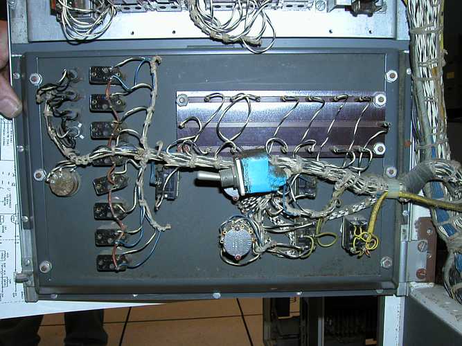
1401 Back Panel Switch
What is the blue switch for behind the 1401 front panel?
| Arnold does remember that he has installed this switch by himself, but I am not sure: The switch behind the 1401 front console may be a private RPQ: It performes a print operation 2 to a NOP. The use for this was: On repeating for active jobs the printing operations have been supressed. These changings have been documented by Arnold in the ALDs.
| 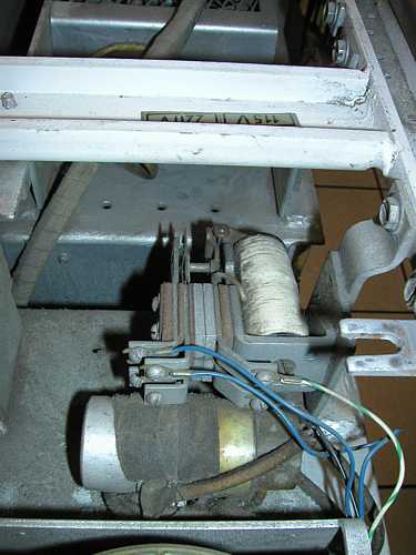
1401 Top Right Relay
What is the relay for on the top right of the 1401?
|
| 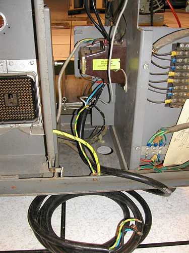
1402 AC Feeder
This is a power connection cord, you can connect this to 3 phases.
380 V/50 Hz Check the wiring plan as reference.
| We have a concern that its wire gauge may not be sufficient; certainly when a full-to-nearly-full system is eventually powered (5 to 13 kVA). Our current thought is to search for an "original" 1402 power cord/plug. (We may have such a cord on the 2nd 1402 unit the Museum owns.) The "landing block" for the AC wires apparently also has some cracks. And the 2nd 1402 we have has a manual circuit breaker, whereas there is none in this 1402.
| 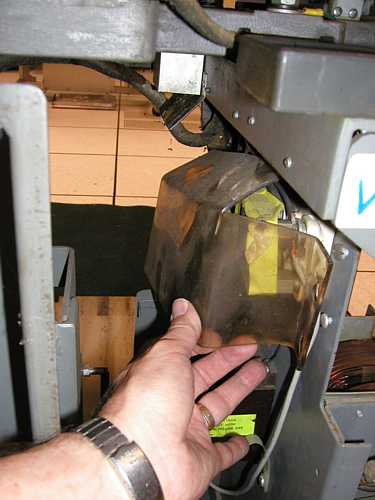
1402 Melted AC Cover
What is the story regarding the melted AC transformer cover?
| This melting is because of normal use, normal heat inside 1402, there was no fire. You can reform it putting onto a heating plate. I'm a little surprised that IBM would design a piece of plastic that normally "melted"! Perhaps the transformer is old and overheating?
| 
1402 Motor Gnd Wire
And the motor ground wire handing in space?
| Please connect this wire to ground Do you recall why it was disconnected?
| 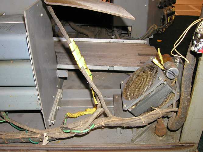
1402-PowerFan_
I'm a little confused. The picture shows a fan:
We're wondering "What did it cool?"
From the picture, it looks like there was something in the place
where the fan is pointing. (We'll have to look at our 2nd 1402...)
| And what was the power fan in the front left of the 1402 cooling? (It looks like whatever it was is missing?). There was no fan when we have received this unit, it worked with out it.
| 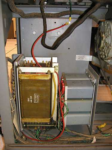
1402 Red Gnd Wire
Do you recall "Why the red ground wire?" in this 1402 picture?:
Looks to be around the ferro-resonant supply.
| |
e-mail from Garner 9/18/2004 7:49 PM
e-mail from Rolf 9/20/2004 12:46 PM
e-mail from Garner 9/29/2004 10:39 AM
e-mail from Garner 9/29/2004 11:21 PM
e-mail from Rolf 4/10/2005
Hello Robert,
Arnold an me have searched for some infomation to answer your questions as follows:
1) In the documents that came with the system, we have not found
the so-called "MFI" or "Machine Feature Index" sheet.
My understanding is that the MFI enumerates the special features/EC's
made
to the machine, such as the "Sterling Feature", "Overlap", or
"Hardware Multiply". Such changes do not seem to be recorded
in the ALD's either. However, feature/ECO wires are definitely present,
as the pictures of SMS card bays B1 & B2 below show.
Do you recall which special features are in this 1401?
Arnold has never used this MFI,
Overlap and HW Multiply should have been built in/installed.
Suggestion: If you have the special test for these features,
then you can check if the features are installed.
2) Do you recall if "Tape Switching" (i.e., 729's can be controlled
by one of two 1401 systems) is a feature in this 1401?
Allen noticed that two of the 729's support tape switching (mod V and II).
Tape switching is not controlled by 1401, to switch the single tapes you will need a
special switch panel.
To controll the relais in 729 are switched by a speacial switchpanel . I think you
won�t need a tape switching because you only have one 1401. (On the lower backside
of the 729 is a manual switch for the relais.)
3) Do you know what the switch was used for behind the front console?
Arnold does remember that he has installed this switch by himself, but I am not sure:
The switch behind the 1401 front console may be a private RPQ: It performes a
print operation 2 to a NOP. The use for this was:
On repeating for active jobs the printing operations have been supressed.
These changings have been documented by Arnold in the ALDs.
Greetings from Arnold and Rolf
Hallo Arnold,

The volunteer team at the Computer History Museum has been
quite busy working on the 1401 system!  If you surf to
http://ibm-1401.info/index.html
you can see the status reports.
One of the actions we're thinking of doing is swapping some
of the corroded mechanical components with those in another
1402 we have at the museum.
We're also working on a plan to apply 50-Hz power to the 1402!

However, as we've inspected the 1402, several questions
have come up.  In particular, it looks like several of
the 1402's AC electrical connections were modified.
If you look at:
http://www.ed-thelen.org/1401Project/ArnoldAssessment.html
you can see labeled pictures of the modifications.
(There are also a few small additions to the 1401 there that
the guys were wondering about too.)

Can you recall why these alterations to the 1402 & 1401 were made?
Is there anything we should be aware of in the 1402 wiring
before applying power?  (For instance, in the 1402's past,
was it ever powered up as part of a stand alone demo perhaps?)

Thanks in advance for your help!

- Robert

p.s.  I will be out next week, but the other folks
on the cc line will be in.
Hello Robert,

as Arnold does recall no modifications have been installed.
The units were connected to 380 Volt, 3 phases, 50 hz,
running was no problem.

The 1402 has never been connected to power supply as stand alone,
allways with the whole system.

Except the rotation directon of the motors nothing else has to
be considered.
Maybe there is a relais installed, which controls the rotation
direction.

We will check the pictures tomorrow and send the comments by mail.

Greetings

Arnold and Rolf
Hallo Arnold, Rolf,

Have you had time to checkout the 1402 & 1401 pictures at
http://www.ed-thelen.org/1401Project/ArnoldAssessment.html

The 3rd picture there, with the non-standard power cord,
certainly appears to be a modification from original.

What is the story regarding the melted AC transformer cover?

And the motor ground wire handing in space?

And what was the power fan in the front left of the 1402
cooling?  (It looks like whatever it was is missing?).

Thanks for your help,

- Robert

On Monday, September 20, 2004, at 12:46 PM, RolfCom@aol.com wrote:

> Hello Robert,
>
> as Arnold does recall no modifications have been installed. The units
> were connected to 380 Volt, 3 phases, 50 hz, running was no problem.
>
> The 1402 has never been connected to power supply as stand alone,
> allways with the whole system.
>
> Except the rotation directon of the motors nothing else has to be
> considered.
> Maybe there is a relais installed, which controls the rotation
> direction.
>
> We will check the pictures tomorrow and send the comments by mail.
>
> Greetings
>
> Arnold and Rolf
>
Arnold, Rolf,

Thanks for your reply!
Some followup comments:

> >> This is a power connection cord, you can connect this to 3 phases.
> 380 V/50 Hz
> Check the wiring plan as reference.

We have a concern that its wire gauge may not be sufficient; certainly
when a full-to-nearly-full system is eventually powered (5 to 13 kVA).
Our current thought is to search for an "original" 1402 power cord/plug.
(We may have such a cord on the 2nd 1402 unit the Museum owns.)
The "landing block" for the AC wires apparently also has some cracks.
And the 2nd 1402 we have has a manual circuit breaker, whereas
there is none in this 1402.

> And the motor ground wire handing in space?
> >> Please connect this wire to ground

Do you recall why it was disconnected?

> And what was the power fan in the front left of the 1402
> cooling? (It looks like whatever it was is missing?).
> >> There was no fan when we have received this unit, it worked with
> out it.

I'm a little confused.  The picture shows a fan:
http://www.ed-thelen.org/1401Project/1402-PowerFan_-.jpg
We're wondering "What did it cool?"
 From the picture, it looks like there was something in the place
where the fan is pointing.  (We'll have to look at our 2nd 1402...)

> What is the story regarding the melted AC transformer cover?
> >> This melting is because of normal use, normal heat inside 1402,
> there was no fire.
> You can reform it putting onto a heating plate.

I'm a little surprised that IBM would design a piece of plastic
that normally "melted"!   Perhaps the transformer is old and
overheating?

Regarding the other pictures for you on the web site:

Do you recall "Why the red ground wire?" in this 1402 picture?:
http://www.ed-thelen.org/1401Project/1402-RedGndWire-.jpg
Looks to be around the ferro-resonant supply.

What is the blue switch for behind the 1401 front panel?
http://www.ed-thelen.org/1401Project/1401-BackPanelSwitch-.jpg

What is the relay for on the top right of the 1401?
http://www.ed-thelen.org/1401Project/1401-TopRightRelay-.jpg

Thanks again,

- Robert

p.s.  We'll be checking the 380-VAC wiring with a 500V "Megger", etc.


On Wednesday, September 29, 2004, at 11:30 AM, RolfCom@aol.com wrote:

> Hello
>
> The 3rd picture there, with the non-standard power cord,
> certainly appears to be a modification from original.
> >> This is a power connection cord, you can connect this to 3 phases.
> 380 V/50 Hz
> Check the wiring plan as reference.
>
> What is the story regarding the melted AC transformer cover?
> >> This melting is because of normal use, normal heat inside 1402,
> there was no fire.
> You can reform it putting onto a heating plat.
>
> And the motor ground wire handing in space?
> >> Please connect this wire to ground
>
> And what was the power fan in the front left of the 1402
> cooling? (It looks like whatever it was is missing?).
> >> There was no fan when we have received this unit, it worked with
> out it.
>
> Greetings
>
> Arnold & Rolf
return to main page